1. BMS Development Process Overview
The development of a bms system is a complex engineering process that requires careful planning, design, testing, and validation to ensure it meets all functional, safety, and performance requirements. A well-structured development process is essential for creating a reliable battery management system that can effectively monitor and control battery packs in various applications, from electric vehicles to energy storage systems.
Modern bms system development follows systematic approaches that integrate hardware and software engineering with rigorous testing methodologies. This comprehensive process ensures that the final product is not only functional but also safe, efficient, and compliant with relevant industry standards.
The development lifecycle of a bms system typically spans several phases, starting from initial concept and requirements analysis through design, implementation, testing, production, and ongoing maintenance. Each phase has specific objectives, deliverables, and quality gates that must be satisfied before proceeding to the next stage.
Effective battery management system development requires close collaboration between various engineering disciplines, including electrical, software, mechanical, and systems engineering. This interdisciplinary approach ensures that all aspects of the bms system are considered, from hardware design and software algorithms to thermal management and mechanical integration.
BMS Development Lifecycle Phases
- 前期分析阶段 (Preliminary Analysis Phase)
- 产品设计开发阶段 (Product Design & Development Phase)
- 产品生产运营阶段 (Production & Operation Phase)
- 持续改进与维护 (Continuous Improvement & Maintenance)
1.1 V-Model Based BMS Development
The bms system development process is increasingly adopting the V-model approach, which provides a structured framework for ensuring that each development phase is verified and validated through corresponding testing activities. This model emphasizes the importance of testing throughout the development lifecycle, not just at the end.
In the V-model for battery management system development, the left side of the "V" represents the design and development stages, progressing from requirements definition to detailed design. The right side represents the testing and validation stages, which correspond to each development stage, ensuring that each design element meets its specified requirements.
This approach is particularly beneficial for bms system development because it ensures that potential issues are identified and addressed early in the process, reducing the cost and complexity of fixes later in the lifecycle. Each verification step confirms that the design meets the requirements, while validation ensures that the final product meets the intended use and customer needs.
The V-model facilitates traceability throughout the battery management system development process, allowing engineers to track each requirement through design, implementation, and testing phases. This traceability is essential for demonstrating compliance with regulatory standards and for efficiently troubleshooting issues that may arise during development or in the field.
The BMS Development V-Model
Design Stages
- Requirements Specification
- System Architecture Design
- Hardware & Software Design
- Component Selection & Sizing
- Detailed Design Implementation
Verification Stages
- Requirements Validation
- Architecture Verification
- Module & Unit Testing
- Integration Testing
- System Validation & Qualification
1.2 BMS Development Standards and Specifications
Developing a bms system requires adherence to a variety of international standards and specifications that govern safety, performance, and reliability. These standards ensure that the battery management system operates safely under all conditions and meets the performance expectations of the application.
Key standards for bms system development include ISO 26262 for functional safety in automotive applications, IEC 62133 for safety requirements for secondary lithium cells and batteries, and UL 1642 for lithium-ion battery safety. These standards provide detailed requirements for design, testing, and validation of battery management systems.
In addition to general safety standards, battery management system development must also consider application-specific standards. For example, automotive BMS must comply with ISO 15118 for communication between electric vehicles and charging infrastructure, while industrial energy storage systems may need to meet IEEE standards for energy storage systems.
Compliance with these standards is not only a regulatory requirement but also a way to ensure that the bms system is robust and reliable. The standards provide a framework for risk assessment, design validation, and production quality control, helping manufacturers produce BMS products that meet the highest industry standards.
Standards also evolve over time to address new technologies and emerging risks, so battery management system developers must stay current with the latest revisions and new standards that may impact their products.
Key BMS Standards and Specifications
| Standard | Focus Area |
|---|---|
| ISO 26262 | Functional safety for automotive systems |
| IEC 62133 | Safety requirements for secondary batteries |
| UL 1642 | Lithium-ion battery safety standard |
| SAE J1772 | Electric vehicle conductive charging system |
| ISO 15118 | Vehicle to grid communication |
| IEC 61508 | Functional safety of electrical/electronic systems |
1.3 BMS R&D Process
The research and development (R&D) process for a bms system is a systematic, iterative approach that transforms conceptual ideas into a validated product ready for production. This process combines theoretical research with practical engineering to develop innovative solutions that address the specific challenges of battery management.
The R&D process for a battery management system typically begins with technology scouting and feasibility studies to identify promising approaches and assess their practicality. This initial phase involves reviewing existing technologies, identifying gaps, and exploring new concepts that could improve BMS performance, safety, or cost-effectiveness.
Once promising concepts are identified, the bms system R&D process moves into the prototype development phase. This involves creating functional prototypes of key components or subsystems to test and validate new technologies or approaches. Prototyping allows engineers to evaluate performance, identify issues, and make necessary adjustments before committing to full-scale development.
Testing is a critical component of the battery management system R&D process, with extensive validation performed at both the component and system levels. This includes bench testing, environmental testing, and field trials under realistic operating conditions. The data collected during testing informs design iterations and helps ensure that the final product meets all performance and safety requirements.
The R&D process for a bms system is highly iterative, with multiple cycles of design, testing, and refinement needed to achieve the desired performance characteristics. This iterative approach allows for continuous improvement and ensures that the final product is optimized for its intended application.
BMS R&D Process Flow
Concept Exploration
Identifying new technologies and approaches for battery management
Experimental Validation
Laboratory testing of new concepts and technologies
Prototype Development
Building functional prototypes of key components
Performance Testing
Comprehensive testing under various conditions
Iterative Improvement
Refining designs based on test results
2. BMS Product Preliminary Analysis Phase
The preliminary analysis phase is the foundation of successful bms system development, providing the roadmap for the entire product lifecycle. This critical phase involves gathering and analyzing information to define the product's purpose, requirements, and constraints before significant resources are invested in design and development.
During this phase, stakeholders from various disciplines collaborate to ensure that all aspects of the battery management system are considered, from technical requirements to market needs. The output of this phase is a comprehensive set of requirements and a clear understanding of the product's feasibility, which guides all subsequent development activities.
Effective preliminary analysis is essential for minimizing risks in bms system development. By thoroughly examining the product's requirements, potential challenges, and safety considerations upfront, developers can avoid costly redesigns and delays later in the development process.
The preliminary analysis phase sets the stage for the entire battery management system development lifecycle, ensuring that the product being developed aligns with market needs, technical capabilities, and safety requirements. A well-executed preliminary analysis increases the likelihood of developing a successful product that meets all stakeholder expectations.
Preliminary Analysis Phase Activities
Requirements Documentation
Capturing and documenting all functional and non-functional requirements
Feasibility Assessment
Evaluating technical, economic, and operational feasibility
Risk Identification
Identifying potential safety and performance risks
Market Analysis
Assessing market needs and competitive landscape
2.1 BMS Product Requirements Analysis
Requirements analysis is a critical step in bms system development, involving the systematic collection, documentation, and prioritization of all functional and non-functional requirements that the product must satisfy. This process ensures that all stakeholder needs are clearly understood and translated into specific, measurable requirements.
Functional requirements for a battery management system define what the system must do, including monitoring battery parameters, balancing cells, protecting against unsafe conditions, and communicating with external systems. These requirements specify the core functionality that enables the BMS to manage the battery pack effectively.
Non-functional requirements for a bms system include performance characteristics, safety requirements, reliability metrics, environmental constraints, and interface specifications. These requirements define how well the BMS must perform its functions, such as response time, measurement accuracy, operating temperature range, and communication protocols.
Requirements analysis for a battery management system involves close collaboration with various stakeholders, including customers, system integrators, regulatory experts, and technical specialists. This collaborative approach ensures that all perspectives are considered and that the resulting requirements are comprehensive and realistic.
The outcome of requirements analysis is a well-documented requirements specification that serves as the foundation for bms system design and development. This document should be clear, concise, and testable, providing a unambiguous reference for evaluating whether the final product meets its intended requirements.
BMS Requirements Classification
Functional Requirements
- Cell voltage monitoring with specified accuracy
- Pack current and temperature measurement
- Cell balancing functionality
- Protection against overcharge, over-discharge, and short circuits
- State of Charge (SOC) and State of Health (SOH) estimation
Non-Functional Requirements
- Operating temperature range: -40°C to +85°C
- Communication latency < 10ms
- MTBF (Mean Time Between Failures) > 10,000 hours
- Compliance with ISO 26262 ASIL B
- Power consumption < 100mW in standby mode
2.2 BMS Product Feasibility Analysis
Feasibility analysis evaluates whether developing a proposed bms system is technically possible, economically viable, and operationally feasible. This critical assessment helps decision-makers determine whether to proceed with development, modify the concept, or abandon the project before significant resources are invested.
Technical feasibility for a battery management system involves assessing whether the required technology exists or can be developed within the project constraints. This includes evaluating component availability, technical expertise requirements, development tools, and integration challenges with the target battery system.
Economic feasibility analysis for a bms system examines the cost of development, production, and maintenance against the expected revenue or benefits. This includes analyzing development costs, material costs, manufacturing expenses, and potential market pricing to determine if the product can be developed and sold at a profit.
Operational feasibility considers whether the battery management system can be effectively integrated into existing operations, including manufacturing processes, supply chains, and customer applications. This analysis evaluates factors such as production capabilities, testing requirements, and compatibility with existing systems.
The feasibility analysis for a bms system should also consider regulatory and compliance factors, assessing whether the product can meet all applicable standards and regulations within the desired timeframe. This includes evaluating certification requirements and potential testing costs.
Feasibility Analysis Criteria
Feasibility Assessment Outcomes
The feasibility analysis results in one of the following recommendations:
- Proceed: The project is feasible and should move forward as planned
- Modify: The project requires adjustments to improve feasibility
- Postpone: The project should be delayed until feasibility can be improved
- Abandon: The project is not feasible and should be discontinued
2.3 BMS Product Safety Risk Analysis
Safety risk analysis is a critical component of bms system development, identifying potential hazards associated with battery operation and determining the measures needed to mitigate these risks. Given the safety-critical nature of battery systems, a comprehensive risk analysis is essential to ensure safe operation under all conditions.
The risk analysis process for a battery management system begins with hazard identification, systematically identifying all potential safety hazards that could arise from battery operation or failure. These hazards include thermal runaway, overcharging, short circuits, overheating, and mechanical damage, among others.
Once hazards are identified, a risk assessment is performed to evaluate the severity and likelihood of each potential hazardous event. This assessment considers factors such as the potential for injury, property damage, environmental impact, and the probability of the event occurring under various operating conditions.
Based on the risk assessment, risk mitigation strategies are developed to reduce the identified risks to an acceptable level. These strategies may include design modifications to the bms system, additional safety features, protective mechanisms, or operational procedures that minimize exposure to hazards.
Safety risk analysis for a battery management system is an iterative process that continues throughout the product lifecycle. As the design evolves and new information becomes available, the risk analysis is updated to ensure that all potential safety concerns are addressed before the product reaches the market.
Regulatory requirements often mandate specific risk analysis methodologies for bms system development, such as Failure Mode and Effects Analysis (FMEA) or Hazard and Operability Study (HAZOP). These structured approaches ensure that risk analysis is comprehensive and systematic.
BMS Safety Risk Assessment Matrix
| Severity → Likelihood ↓ |
Minor (1) | Moderate (2) | Serious (3) | Severe (4) | Catastrophic (5) |
|---|---|---|---|---|---|
| Remote (1) | Low | Low | Medium | Medium | High |
| Unlikely (2) | Low | Medium | Medium | High | Critical |
| Possible (3) | Medium | Medium | High | Critical | Critical |
| Likely (4) | Medium | High | Critical | Critical | Critical |
| Certain (5) | High | Critical | Critical | Critical | Critical |
Key BMS Safety Hazards
- Thermal runaway due to overcharging
- Cell imbalance leading to overvoltage conditions
- Short circuit conditions
- Over-temperature operation
- Communication failures affecting safety functions
3. BMS Product Design and Development Phase
The design and development phase transforms the requirements and specifications from the preliminary analysis phase into a functional bms system prototype. This phase involves detailed design of both hardware and software components, followed by integration and testing to ensure that all requirements are met.
Effective design and development of a battery management system requires a structured approach that integrates hardware and software engineering with rigorous testing methodologies. This phase is critical for ensuring that the final product is reliable, efficient, and safe for its intended application.
The design and development phase for a bms system typically follows a systematic process, starting with architecture design, followed by detailed component design, implementation, and verification testing. This structured approach ensures that each design decision is validated against the requirements before proceeding to the next stage.
Throughout the design and development phase, close collaboration between hardware and software teams is essential to ensure that the battery management system components work seamlessly together. This collaboration helps identify and resolve integration issues early in the development process, reducing the need for costly redesigns later.
The outcome of the design and development phase is a validated prototype that meets all functional and non-functional requirements, providing a solid foundation for moving into production. This prototype undergoes extensive testing to ensure that it performs as expected under all specified operating conditions.
Design and Development Phase Workflow
System Architecture Design
Defining the overall structure and components of the BMS
Hardware Component Design
Designing circuit boards, sensors, and power management components
Software Algorithm Development
Developing control algorithms, monitoring functions, and communication protocols
Prototype Construction
Building functional prototypes for testing and validation
Integration and Verification
Testing the integrated system against requirements
3.1 BMS Hardware Design Process Control
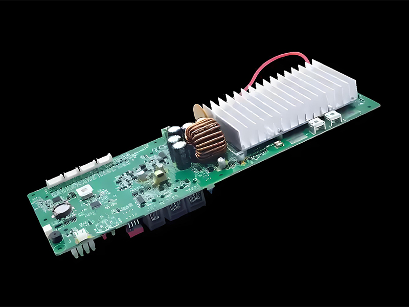
Hardware design process control ensures that the bms system hardware components are designed, tested, and validated in a systematic manner that meets all requirements and quality standards. This structured approach minimizes design errors, reduces development time, and ensures that the final hardware is reliable and manufacturable.
The hardware design process for a battery management system begins with schematic design, where engineers define the electrical circuits that will implement the required functionality. This includes selecting appropriate components, defining interfaces, and ensuring that all electrical requirements are met, such as voltage levels, current capacities, and power consumption.
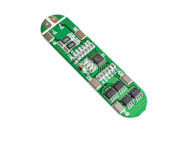
Printed Circuit Board (PCB) layout is a critical stage in bms system hardware design, involving the physical placement of components and routing of electrical connections. PCB design must consider factors such as signal integrity, power distribution, thermal management, and electromagnetic compatibility (EMC) to ensure reliable operation.
Component selection is a key aspect of battery management system hardware design, with careful consideration given to factors such as accuracy, reliability, temperature range, cost, and availability. Critical components such as voltage sensors, current shunts, MOSFETs for protection, and microcontrollers must be carefully selected to meet the performance requirements.
Hardware design verification involves testing prototypes to ensure that they meet all electrical and mechanical requirements. This includes bench testing, environmental testing, and reliability testing to validate performance under various conditions. Any issues identified during testing are addressed through design iterations until the hardware meets all specifications.
Throughout the hardware design process, documentation is maintained to ensure traceability from requirements to design decisions and test results. This documentation is essential for regulatory compliance, manufacturing, and future maintenance of the bms system.
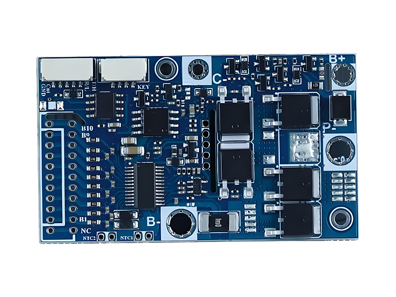
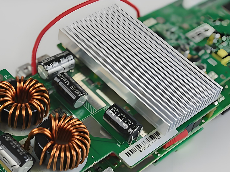
BMS Hardware Design Elements
Core Hardware Components
- • Microcontroller Unit (MCU) with sufficient processing power
- • Voltage sensing circuitry with high accuracy
- • Current measurement system (shunt or Hall effect)
- • Temperature sensors (NTC or thermistors)
- • Cell balancing circuitry
- • Protection MOSFETs or relays
- • Communication interfaces (CAN, UART, SMBus, etc.)
- • Power management circuitry
Design Considerations
- • Measurement accuracy and resolution
- • Noise immunity and signal filtering
- • Thermal management and heat dissipation
- • ESD protection and surge immunity
- • Power efficiency and standby current
- • Physical size and form factor
- • Cost optimization
- • Manufacturing feasibility
Hardware Testing Requirements
3.2 BMS Software Design Process Control
Software design process control ensures that the bms system software is developed in a structured, systematic manner that meets all functional requirements, safety standards, and performance criteria. This controlled approach ensures software reliability, maintainability, and compliance with relevant industry standards.
The software design process for a battery management system begins with requirements analysis and software architecture design, defining the overall structure of the software, including modules, interfaces, and data flows. This architecture provides a blueprint for the development team and ensures that all requirements are addressed.
Algorithm development is a critical component of bms system software design, involving the creation of sophisticated algorithms for State of Charge (SOC) estimation, State of Health (SOH) monitoring, cell balancing control, and protection functions. These algorithms must be accurate, efficient, and robust to ensure reliable battery operation.
Software implementation follows a structured coding process, with adherence to coding standards and best practices to ensure code quality, readability, and maintainability. The battery management system software typically includes real-time operating system (RTOS) components to handle the time-critical functions required for battery monitoring and control.
Software testing is performed at multiple levels, including unit testing, integration testing, and system testing, to ensure that all functions work correctly and meet the specified requirements. This testing includes both functional testing to verify correct operation and non-functional testing to validate performance, reliability, and safety.
Software design process control also includes configuration management to track changes, version control to manage software releases, and documentation to ensure that the bms system software can be maintained and updated throughout its lifecycle.
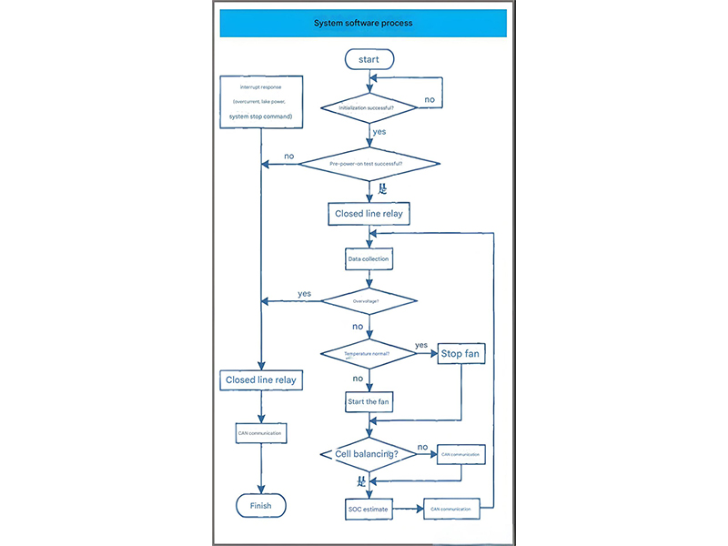
BMS Software Architecture
High-Level Functions:
- SOC/SOH Estimation Algorithms
- Battery Protection Logic
- Cell Balancing Control
- Diagnostic Functions
- User Interface
Services:
- Communication Protocols (CAN, UART)
- Data Logging & Storage
- Calibration Management
- Error Handling & Reporting
Hardware Interfaces:
- ADC Drivers for Voltage/Current
- Temperature Sensor Drivers
- GPIO Control for Relays/MOSFETs
- Timer & PWM Controllers
- Memory Interfaces
Key BMS Software Algorithms
SOC Estimation
Combination of Coulomb counting, open circuit voltage measurement, and Kalman filtering
SOH Monitoring
Capacity fade tracking, internal resistance monitoring, and cycle counting
Cell Balancing
Active and passive balancing algorithms with intelligent triggering conditions
3.3 BMS Integration Verification Testing
Integration verification testing ensures that the hardware and software components of the bms system work together correctly as a complete system and that the integrated system meets all specified requirements. This critical testing phase validates that the individual components, which may have been tested separately, function properly when combined.
Integration testing for a battery management system typically follows a systematic approach, starting with the integration of related components into subsystems, followed by testing of these subsystems, and ultimately testing the complete system. This incremental approach helps isolate and identify integration issues early in the testing process.
Functional verification testing ensures that the integrated bms system performs all required functions correctly, including monitoring, protection, balancing, and communication functions. This testing validates that the system behaves as specified under various operating conditions and input scenarios.
Performance testing evaluates the battery management system's performance characteristics, such as measurement accuracy, response time, communication latency, and power consumption. This testing ensures that the system meets all non-functional requirements and performs adequately under expected operating conditions.
Environmental testing subjects the integrated bms system to various environmental conditions, including temperature extremes, humidity, vibration, and shock, to verify that it continues to operate correctly under these conditions. This testing is essential for ensuring reliability in real-world applications.
Safety verification testing ensures that the bms system correctly implements all safety functions and protection mechanisms, including overcharge protection, over-discharge protection, short circuit protection, and over-temperature protection. This testing often involves fault injection to verify that the system responds appropriately to abnormal conditions.
The outcome of integration verification testing is a validated battery management system that meets all specified requirements and is ready for production. Any issues identified during testing are addressed through design modifications and retesting until all requirements are satisfied.
BMS Integration Testing Hierarchy
Level 1: Component Testing
Verification of individual hardware and software components
Level 2: Module Testing
Testing of integrated hardware modules and software modules
Level 3: Subsystem Testing
Verification of complete subsystems (measurement, protection, communication)
Level 4: System Integration Testing
Testing of the complete BMS with all subsystems integrated
Level 5: Battery Pack Testing
Verification of BMS performance with actual battery pack
Test Coverage Matrix
| Test Type | L1 | L2 | L3 | L4 | L5 |
|---|---|---|---|---|---|
| Functional Testing | |||||
| Performance Testing | |||||
| Environmental Testing | |||||
| Safety Testing | |||||
| Compatibility Testing |
4. BMS Product Production and Operation Phase
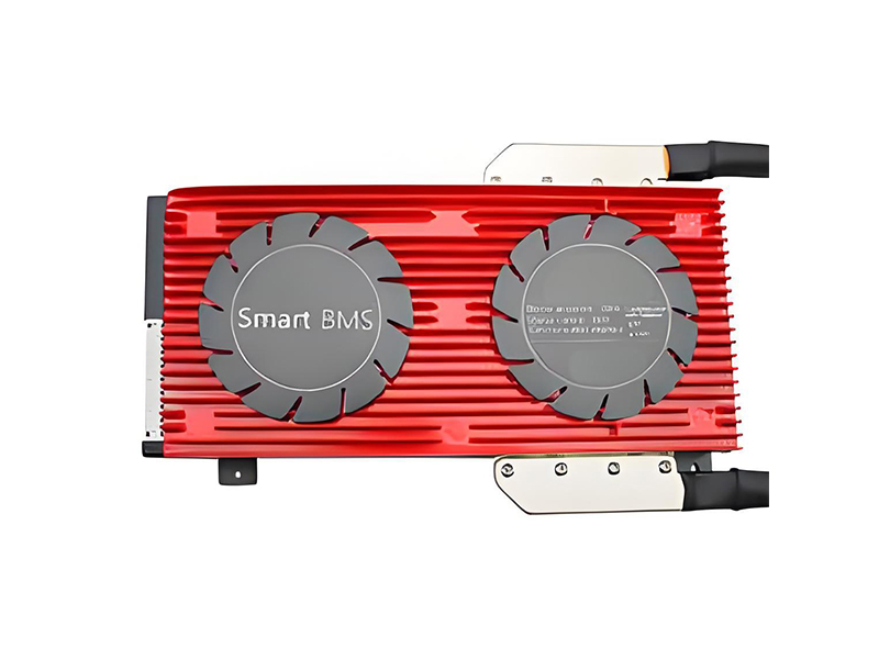
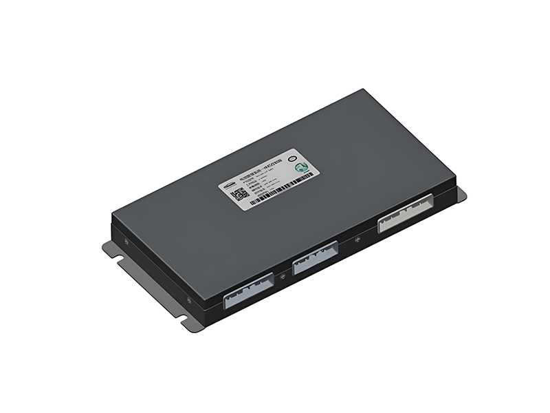
The production and operation phase encompasses the manufacturing of the bms system, its integration into battery packs, and its ongoing operation in the field. This phase ensures that the designed product can be efficiently manufactured at scale while maintaining quality, and that it continues to perform reliably throughout its operational life.
Production of a battery management system requires careful planning of manufacturing processes, including PCB assembly, component testing, system integration, and final verification. Quality control measures are implemented throughout the production process to ensure that each unit meets the required specifications and performance standards.
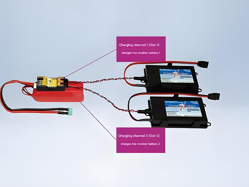
Once manufactured, the bms system is integrated into battery packs, where it works with the battery cells and other components to provide safe, efficient operation. This integration process includes mechanical installation, electrical connection, and system-level testing to ensure proper functionality.
The operational phase involves monitoring the performance of the battery management system in real-world applications, collecting data on its performance, and addressing any issues that arise. This phase may include remote monitoring, firmware updates, and maintenance activities to ensure continued reliability and performance.
Throughout the production and operation phase, feedback from manufacturing processes and field performance is collected and analyzed to identify opportunities for improvement. This feedback loop is essential for continuous improvement of the bms system design, manufacturing processes, and support services.
Production and Operation Lifecycle
PCB Production
Component Assembly
System Testing
Pack Integration
Field Operation
Key Activities in Production & Operation
Manufacturing Process Control
Ensuring consistent quality during mass production
Quality Assurance & Testing
100% testing of finished products before shipment
Supply Chain Management
Ensuring component availability and traceability
Field Performance Monitoring
Tracking BMS performance in real-world applications
Maintenance & Support
Providing technical support and firmware updates
4.1 BMS Production
BMS production involves the manufacturing and assembly of bms system components into finished products, following strict quality control procedures to ensure consistency and reliability. The production process must be designed to efficiently produce high-quality units at the required volume while meeting all technical specifications.
The production process for a battery management system typically begins with PCB manufacturing, where the printed circuit boards are fabricated according to the design specifications. This involves processes such as photolithography, etching, and drilling to create the conductive paths and component mounting points.
Component assembly is the next stage in bms system production, involving the placement and soldering of electronic components onto the PCBs. This process is typically automated using surface mount technology (SMT) equipment for high-volume production, with automated optical inspection (AOI) used to verify correct component placement and soldering quality.
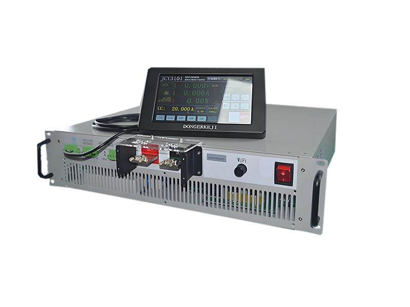
After assembly, each battery management system undergoes a series of tests to verify functionality and performance. This includes electrical testing to ensure correct operation, functional testing to validate all features, and calibration to ensure measurement accuracy. Units that pass these tests proceed to final assembly and packaging.
Quality control is implemented throughout the bms system production process, with inspections and tests at critical stages to identify and address any issues. Statistical process control (SPC) techniques are often used to monitor production processes and identify trends that could indicate potential quality problems.
Production documentation is maintained for each battery management system unit, including test results, component traceability information, and manufacturing data. This documentation is essential for quality assurance, regulatory compliance, and troubleshooting any issues that may arise in the field.
BMS Production Process
PCB Manufacturing
Fabrication of printed circuit boards to exact specifications
Component Placement
Automated placement of SMT and through-hole components
Soldering & Inspection
Reflow soldering and automated optical inspection
Functional Testing
Comprehensive testing of all BMS functions and performance
Calibration & Programming
Software programming and performance calibration
Production Quality Control Measures
Testing at each production stage to catch issues early
Statistical sampling to verify production quality
Component and production history tracking
Real-time monitoring of production parameters
4.2 BMS Sales and Maintenance
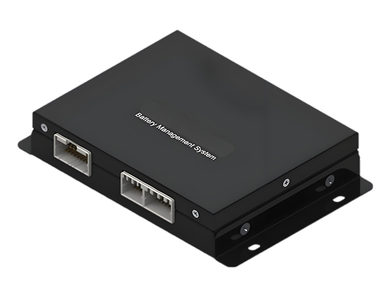
BMS sales and maintenance encompasses the processes involved in bringing the bms system to market, supporting customers during installation and operation, and providing ongoing maintenance to ensure continued performance. This phase is critical for customer satisfaction and ensuring that the product delivers value throughout its operational life.
The sales process for a battery management system involves understanding customer requirements, providing technical specifications and documentation, and demonstrating how the product meets the customer's needs. This may include providing samples for evaluation, conducting technical presentations, and assisting with system integration planning.
Customer support is an essential aspect of bms system sales, involving technical assistance during installation, commissioning, and initial operation. This support ensures that the BMS is properly integrated into the customer's system and configured to meet their specific requirements.
Maintenance of a battery management system includes both preventive and corrective activities to ensure continued reliable operation. Preventive maintenance may involve regular performance checks, firmware updates to improve functionality or address issues, and calibration verification. Corrective maintenance involves troubleshooting and repairing any issues that arise during operation.
Remote monitoring capabilities are increasingly important for battery management system maintenance, allowing service teams to monitor performance, detect issues early, and even resolve some problems without on-site visits. This remote capability improves service response times and reduces maintenance costs.
Feedback from customers and field service teams is valuable for improving the bms system and related services. This feedback is used to identify opportunities for product enhancements, address common issues, and improve documentation and support processes.
The sales and maintenance phase also includes managing end-of-life considerations for the battery management system, such as providing replacement options, recycling guidance, and supporting system upgrades or retrofits as technology evolves.
BMS Sales and Support Framework
Maintenance Service Levels
- • Regular firmware/software updates
- • Calibration verification and adjustment
- • Performance data analysis
- • Inspection of connections and components
- • Preventive replacement of wear items
- • Troubleshooting and diagnostics
- • Component replacement
- • Repair of electrical issues
- • Software bug fixes
- • System recovery and reconfiguration
- • Performance optimization
- • Feature upgrades
- • Integration with new systems
- • Customization for specific applications
- • Training and knowledge transfer