BMS Hardware Design | Industry Leading Solutions

BMS Hardware Design Excellence

Comprehensive engineering solutions for Battery Management Systems, featuring advanced battery control module technology and industry-leading design methodologies.

Hardware Overall Scheme Design

The Hardware Overall Scheme Design serves as the foundational blueprint for any Battery Management System (BMS), outlining the complete architecture and integration strategy for all components. This phase involves defining system requirements based on application specifics, whether for automotive, industrial, or energy storage applications. A well-designed overall scheme ensures that the BMS can effectively monitor, protect, and optimize battery performance throughout its lifecycle.

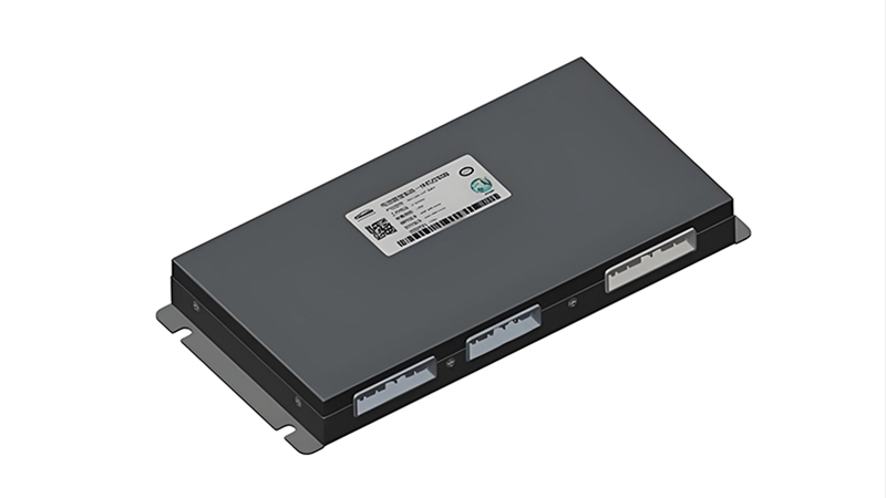
Central to this design is the battery control module, which acts as the intelligence hub of the BMS. The battery control module coordinates all other system components, processing data from sensors and executing control algorithms to maintain optimal battery conditions. During the overall scheme design, engineers must determine the appropriate processing power, communication interfaces, and I/O capabilities required for the battery control module to meet system demands.

Key considerations in this phase include:

  • Definition of functional requirements and performance metrics
  • Selection of appropriate microcontroller units (MCUs) for the battery control module
  • Determination of sensor placement and data acquisition strategies
  • Design of communication protocols (CAN, LIN, Ethernet) for system integration
  • Thermal management strategy for all components, including the battery control module
  • Physical layout planning for optimal signal integrity and EMI/EMC performance
  • Redundancy and fault tolerance considerations

The overall scheme design must balance performance, cost, reliability, and manufacturability. It typically involves creating block diagrams, system architecture documents, and initial component selection lists. Simulation tools are often employed to validate the proposed architecture before moving to detailed design phases. The battery control module specifications are finalized during this stage, establishing the processing capabilities and functional boundaries that will guide subsequent design decisions.

BMS Hardware Overall Architecture Diagram showing the battery control module as central hub connecting various subsystems

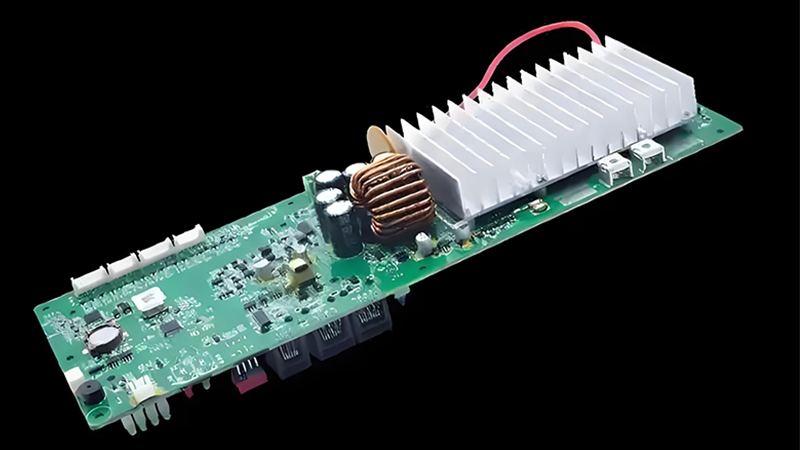
BMS Hardware Architecture

Diagram illustrating the overall hardware scheme with the battery control module at its core, connecting to sensing, power, communication, and protection subsystems.

System Requirements Matrix

Requirement Category Key Specifications Relevance to battery control module
Voltage Monitoring ±1mV accuracy, 1-24 cells per channel Primary data input for control algorithms
Current Measurement ±0.5% accuracy, range -500A to +500A Used for SOC calculation and protection
Temperature Sensing ±1°C accuracy, up to 16 sensors Critical for thermal management algorithms
Processing Power 32-bit MCU, ≥100MHz, ≥256KB Flash Determines computational capabilities
Communication CAN 2.0B, LIN, optional Ethernet Enables data exchange with external systems

Power System Output and Protection Design

The Power System Output and Protection Design is critical for ensuring safe and reliable operation of the BMS and connected battery pack. This subsystem is responsible for regulating power distribution within the BMS, providing stable voltages to sensitive components like the battery control module, while implementing robust protection mechanisms against fault conditions.

The power system typically includes multiple voltage rails to accommodate different components: a 3.3V rail for microcontrollers and digital circuits within the battery control module, a 5V rail for sensors and communication interfaces, and potentially higher voltage rails for drivers and actuators. Designers must carefully calculate power requirements for each rail, considering both steady-state and transient conditions.

Protection mechanisms are paramount in BMS power design. These include:

  • Overvoltage protection (OVP) to prevent damage from voltage spikes
  • Undervoltage lockout (UVLO) to ensure proper operation during low-voltage conditions
  • Overcurrent protection (OCP) with adjustable trip points for different subsystems
  • Short-circuit protection (SCP) to limit current in fault situations
  • Reverse polarity protection to prevent damage from incorrect connections
  • Thermal shutdown to protect components during excessive temperature conditions

The battery control module plays a supervisory role in the power system, monitoring voltage levels and current flows through dedicated sense circuits. In the event of a fault, the battery control module can trigger protective actions such as disabling power outputs, activating cooling systems, or isolating the battery pack. Power system design must account for worst-case scenarios, including load dumps, transient voltage spikes, and extreme temperature variations.

Efficiency is another key consideration, as power losses generate heat that must be managed. Switch-mode power supplies (SMPS) are commonly used for their high efficiency, though linear regulators may be employed in noise-sensitive areas. Layout techniques such as proper grounding, power plane design, and component placement are critical for minimizing noise and ensuring stable operation of the battery control module and other sensitive components.

Power system block diagram showing voltage regulation circuits and protection mechanisms connected to the battery control module

Power Distribution and Protection Schema

Schematic representation of the power system showing multiple voltage rails, protection circuits, and their interface with the battery control module.

Protection Circuit Response Characteristics

The chart illustrates typical response times of various protection mechanisms, with the battery control module providing supervisory control and system-level response.
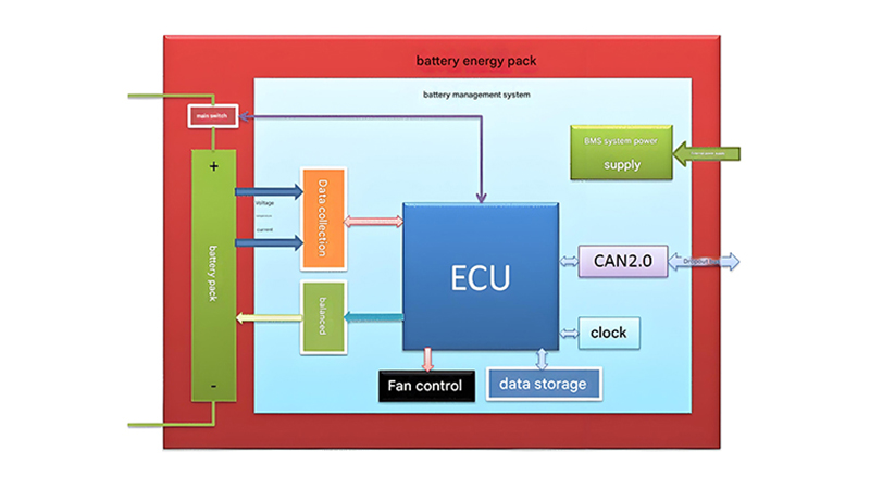
Topology Design

Topology Design refers to the arrangement and interconnection of components within the BMS hardware architecture. This critical design phase determines how the battery control module interacts with other system components, including cell monitoring circuits, current sensors, communication interfaces, and power management subsystems. The chosen topology directly impacts system performance, reliability, cost, and scalability.

Several common BMS topologies are employed in industry, each with distinct advantages and trade-offs:

Centralized Topology

In a centralized topology, all functions including cell monitoring, current measurement, and control algorithms are integrated into a single main board. The battery control module serves as the central processing unit, directly connected to all sensors and actuators.

Advantages include simplified communication, lower latency between measurements and control actions, and potentially lower cost for small to medium-sized battery packs. Disadvantages may include increased wiring complexity and challenges in thermal management as the number of cells increases.

Distributed Topology

A distributed topology utilizes multiple cell monitoring units (CMUs) placed close to battery cells, with each CMU communicating with a central battery control module. This approach reduces wiring complexity and improves signal integrity by minimizing the distance between sensors and cells.

Benefits include easier scalability for large battery packs, improved thermal management through distributed heat generation, and enhanced fault isolation. Challenges include ensuring reliable communication between CMUs and the battery control module, and maintaining synchronization across distributed measurements.

Modular Topology

Modular topology combines aspects of both centralized and distributed approaches, using standardized modules that can be combined to accommodate different battery pack configurations. The battery control module typically manages multiple identical modules, each responsible for a section of the battery pack.

This approach offers excellent scalability, simplified manufacturing, and easier maintenance and repair. It also facilitates design reuse across multiple product lines. The main challenges involve ensuring consistent performance across modules and managing the communication overhead between the battery control module and each module.

Centralized BMS topology diagram showing battery control module connected directly to all sensors and actuators

Centralized Topology

Single-board design with integrated battery control module directly connected to all system components.

Distributed Topology

Decentralized architecture with remote monitoring units and a central battery control module.

Topology Comparison Matrix

Characteristic Centralized Distributed Modular
Scalability Limited (up to ~24 cells) Excellent (hundreds of cells) Very good (modular expansion)
battery control module Complexity High (all functions integrated) Medium (focus on coordination) Medium (module management)
Wiring Complexity High (many long connections) Low (short, localized connections) Medium (standardized interfaces)
Cost (Small Packs) Lowest Higher Higher
Cost (Large Packs) Highest Lower Lowest
Reliability Lower (single point of failure) Higher (fault isolation) Highest (modular redundancy)

Design of BCU, BMC and Balancing Circuit

The Design of BCU, BMC and Balancing Circuit encompasses the core functional elements of a BMS. These components work in concert, with the battery control module acting as the central coordinator to ensure optimal battery performance, safety, and longevity.

Battery Control Unit (BCU)

The BCU represents the primary processing and decision-making element within the battery control module. It typically consists of a high-performance microcontroller with sufficient processing power to execute complex algorithms for State of Charge (SOC), State of Health (SOH), and State of Function (SOF) estimation.

Key BCU design considerations include:

  • Selection of MCU with appropriate processing power, memory, and peripherals
  • Implementation of real-time operating system (RTOS) for deterministic operation
  • Design of redundant processing paths for safety-critical applications
  • Integration of communication interfaces (CAN, LIN, Ethernet) for external connectivity
  • Development of fail-safe mechanisms and watchdog timers
  • Optimization of algorithm execution efficiency for real-time performance

The BCU serves as the "brain" of the battery control module, processing inputs from various sensors, executing control algorithms, and generating outputs to manage the battery system and communicate with external devices.

Battery Monitoring Circuitry (BMC)

The BMC provides the critical sensing functions that supply the battery control module with accurate data about battery conditions. This includes cell voltage monitoring, current measurement, and temperature sensing.

Key BMC design aspects include:

  • High-precision analog-to-digital converters (ADCs) for voltage measurements
  • Isolation techniques to handle high common-mode voltages
  • Current sensing using shunt resistors or Hall-effect sensors
  • Thermistor or thermocouple interfaces for temperature monitoring
  • Filtering circuits to reduce noise and improve measurement accuracy
  • Calibration mechanisms to ensure measurement precision over temperature and time

The BMC must provide measurements with sufficient accuracy and resolution to enable the battery control module to make precise calculations of SOC and other critical parameters. Typically, voltage measurements require accuracy in the millivolt range, while current measurements need to resolve small changes even at high current levels.

Balancing Circuit

Battery cell balancing circuits ensure that individual cells within a battery pack remain at similar charge levels, maximizing capacity utilization and extending battery life. The battery control module monitors cell voltages and activates balancing circuits when significant discrepancies are detected.

There are two primary balancing approaches:

Passive Balancing

Uses resistors to dissipate excess energy from cells with higher charge. This method is simpler and lower cost but less efficient, as energy is wasted as heat. The battery control module activates MOSFET switches to connect balancing resistors to overcharged cells.

Active Balancing

Transfers energy from higher-charge cells to lower-charge cells using inductors, capacitors, or transformers. This method is more complex and expensive but significantly more efficient. The battery control module manages the energy transfer process to optimize balancing speed and efficiency.

Balancing circuit design considerations include current rating, switching speed, thermal management, and efficiency. The battery control module implements algorithms to determine when balancing is needed, which cells to balance, and for how long, based on voltage measurements from the BMC.

Block diagram of BCU showing microcontroller, memory, and communication interfaces within the battery control module

Battery Control Unit (BCU) Architecture

Detailed diagram of the BCU, the processing core within the battery control module, showing key components and interfaces.

Battery monitoring circuit schematic showing voltage, current, and temperature sensing components connected to the battery control module

Battery Monitoring Circuitry (BMC)

Schematic representation of precision sensing circuits that provide critical data to the battery control module.

Active and passive cell balancing circuit diagrams showing energy transfer mechanisms controlled by the battery control module

Cell Balancing Circuits

Comparison of passive and active balancing approaches, illustrating control signals from the battery control module.

BCU Performance Specifications

  • 32-bit ARM Cortex-M7 MCU @ 216 MHz core frequency
  • 1 MB Flash memory, 384 KB RAM for algorithm execution
  • Multiple CAN 2.0B interfaces (up to 8) with 1 Mbps bandwidth
  • 12-bit ADC with 2 MSPS conversion rate for sensor inputs
  • Operating temperature range: -40°C to +105°C
  • ASIL-D compliant design for functional safety
  • Hardware security module (HSM) for secure communication

Balancing Circuit Performance

Comparison of balancing efficiency and speed between passive and active systems, controlled by the battery control module.

Hardware Testing and Validation

Hardware Testing and Validation represents the critical final phase in BMS development, ensuring that the designed hardware meets all functional, performance, and safety requirements. This rigorous process verifies that the battery control module and associated components operate correctly under all anticipated conditions, from normal operation to extreme fault scenarios.

A comprehensive testing strategy encompasses multiple levels of validation, starting with component-level testing and progressing to system-level verification. Each test phase generates data that confirms proper operation of the battery control module and its interaction with other system components.

Component-Level Testing

Individual components and subcircuits are tested to verify their performance against specifications. For the battery control module, this includes:

  • MCU functionality verification, including clock speed, memory access, and peripheral operation
  • Power supply testing to confirm stable operation across voltage ranges and load conditions
  • Analog circuit testing for accuracy, linearity, and noise performance
  • Digital interface validation for communication protocols (CAN, LIN, etc.)
  • Environmental testing of components under temperature extremes and vibration

Component testing often involves using specialized equipment such as oscilloscopes, signal generators, and environmental chambers to simulate various operating conditions and measure performance parameters.

Board-Level Testing

Once individual components are verified, the complete PCB assembly undergoes thorough testing to ensure proper functionality as a system. This includes:

  • Power-up testing to verify correct voltage levels at all points
  • Continuity and isolation testing to confirm proper connections and absence of shorts
  • Functional testing of all battery control module features and interfaces
  • Signal integrity analysis for high-speed digital and analog signals
  • Thermal imaging to identify hot spots during operation
  • Electromagnetic compatibility (EMC) pre-compliance testing

Board-level testing ensures that the physical implementation matches the design intent and that components interact correctly when assembled. This phase often reveals issues related to layout, grounding, or component placement that may not be apparent during component-level testing.

System-Level Validation

The final validation phase tests the complete BMS, including the battery control module, in conjunction with actual battery packs and connected systems. This includes:

  • End-to-end functional testing under normal operating conditions
  • Fault injection testing to verify protection mechanisms
  • Performance testing across temperature extremes and voltage ranges
  • Durability and reliability testing over extended periods
  • Compliance testing against relevant standards (ISO, IEC, SAE, etc.)
  • Integration testing with host systems (vehicle, energy storage system, etc.)

System-level validation confirms that the BMS performs as required in its intended application. This phase often involves using hardware-in-the-loop (HIL) test systems to simulate real-world conditions while measuring the battery control module's response. The data collected during this phase is used to validate design decisions, identify any remaining issues, and document compliance with requirements.

BMS hardware testing setup showing battery control module connected to test equipment for validation

Component and Board Testing

Automated test setup for validating battery control module components and PCB assemblies under various conditions.

Hardware-in-the-Loop (HIL) Testing

Advanced test environment for validating the battery control module under realistic operating conditions using real-time simulation.

Testing Validation Matrix

Test Category Key Test Parameters Acceptance Criteria Relevant Standards
Functional Testing - Voltage measurement accuracy
- Current measurement accuracy
- Communication functionality
- Balancing operation
- Voltage: ±1mV
- Current: ±0.5% of range
- Error-free communication
- Cells balanced to ±5mV
ISO 11898
SAE J1939
Environmental Testing - Temperature cycling
- Vibration testing
- Humidity exposure
- Thermal shock
- Operation from -40°C to +85°C
- No performance degradation after vibration
- No condensation damage
- Survival of 100°C temperature changes
IEC 60068-2
MIL-STD-883H
Electrical Testing - ESD immunity
- EMC emissions
- Voltage transient immunity
- Short circuit protection
- Survival of ±8kV contact discharge
- Compliance with CISPR 25
- Immunity to 12V system transients
- Safe shutdown within 10ms
IEC 61000-4
CISPR 25
ISO 7637
Reliability Testing - Accelerated life testing
- Power cycling
- Thermal cycling
- Humidity testing
- >10,000 hours MTBF
- >10,000 power cycles
- >1,000 thermal cycles
- 95% RH for 1000 hours
IEC 60721
MIL-HDBK-217F

This matrix outlines the comprehensive testing requirements for validating BMS hardware, with particular focus on the battery control module performance under various conditions.

滚动至顶部